
Long Numbered List Randomly Changes
Here’s steps for creating and setting up a new VLAN in the home cluster.
This includes all infrastructure needs: ESX setup, main switch, virtual interfaces in the router, and baseline firewall rules.
Several steps are included, so we outline them here.
This will require updating the main switch, VSPhere, ESX host, and the house router.
Documentation
-
Open the Network VLANs listing, and add a new entry for the VLAN.
Include a name, VLAN Id, subnet and usage.
Page is here: Network VLANs and Subnets
Main Switch Config
The main switch will need to be updated, so VMs in the new VLAN can reach the router.
-
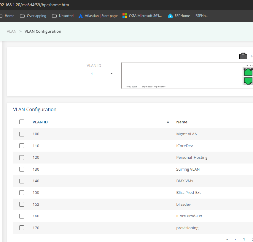
Log into the main switch at: 192.168.1.20.
-
From the main switch UI, add a new VLAN entry, like this:

-
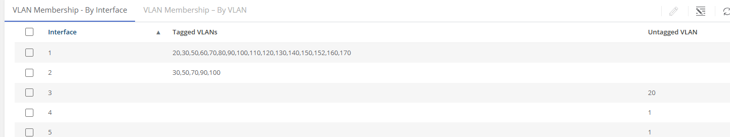
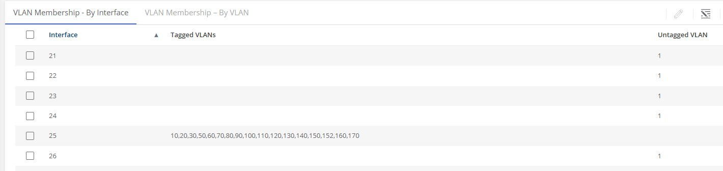
If machines in the VLAN will need to route to other machines or the internet, you will need to add the VLAN ID to the list of VLAN tags for the following switch ports:
-
Port 1 - the trunk connection to the router:
-
Port 25 - the trunk connection to the ESX host:

The above two ports allow VLAN traffic from the ESX host (25) to get routed by OpnSense (via port 1).
-
-
Make a backup of the updated switch configuration, and store it here:
\\192.168.1.211\Backups\Backups\main_switch_1930

VSphere Updates
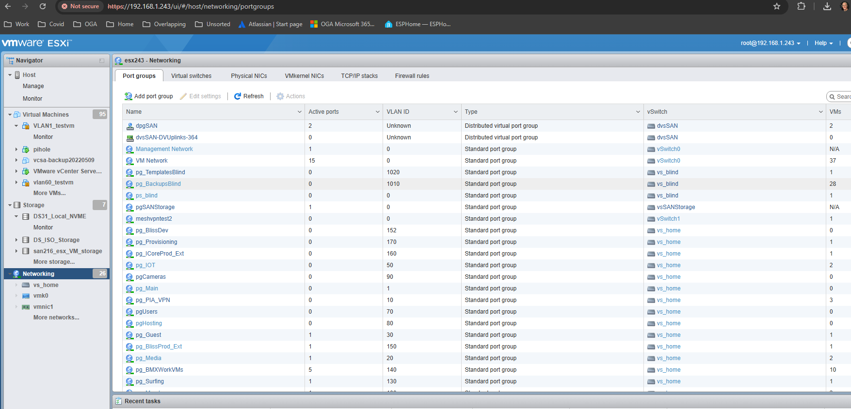
For VMs to use the new VLAN, the ESX host will need a port group that tags any trunked traffic (heading to the router) with the new VLAN Id.
We already have a virtual switch in the ESX host, named: vs_home.
It has a physical adapter that connects to the main switch at port 25.
And, it contains all the VLAN port groups that trunk to the router.
So, we need to add a port group (to our virtual switch in the ESX) for the new VLAN.
-
Open a UI session to the ESX host at: 192.168.1.243.
-
Navigate to the Port Groups tab on the Networking page.
-
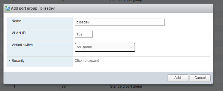
Click Add Port Group, to open the popup.
-
Give the new port group a name. Something that indicates its purpose.
-
Set the new vlanid to match what was reserved above.
-
Choose the virtual switch, vs_home, so traffic from the port group can trunk to the main switch.

-
Click OK to add the new port group for our VLAN.

VSphere
We need to confirm the new port group is accessible in VCenter.
-
Open the web UI for the VSphere instance at: 192.168.1.242.
-
Navigate to the Networking tree, for the datacenter, and verify the new port group is listed.
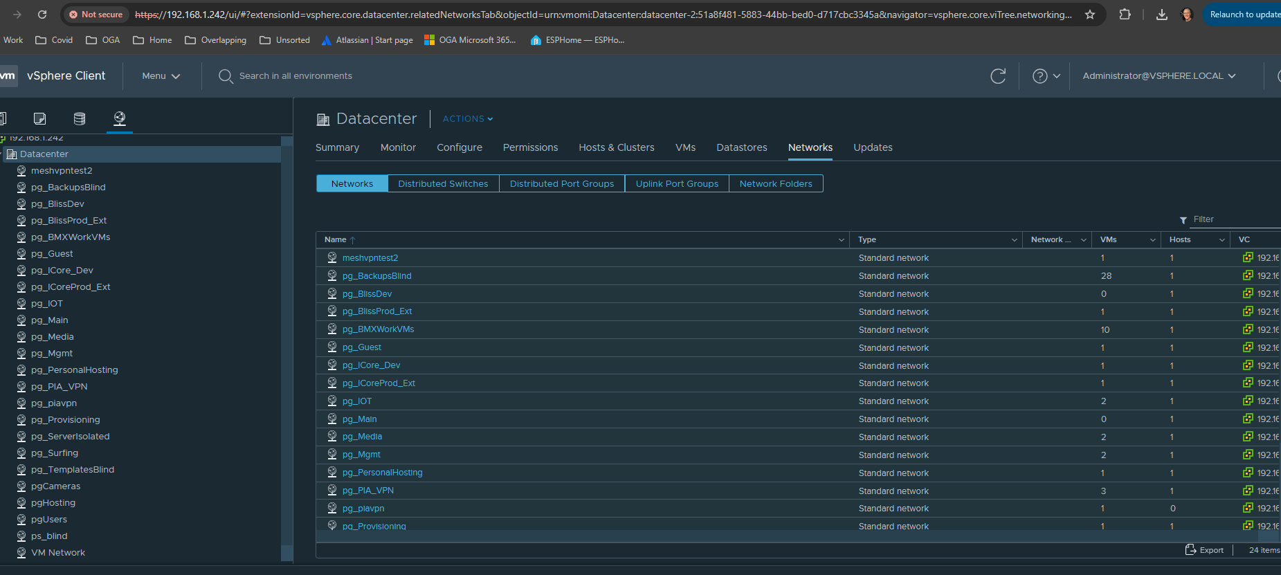
-
Once confirmed, we can now assign VM network adapters to the new port group.

OpnSense
Last, we need to configure the main router for the new VLAN.
This includes:
-
Adding a new VLAN, so traffic is recognized
-
Creating a virtual interface for the new VLAN
-
Adding DHCP service to the VLAN
-
Adding firewall rules for internet visibility
-
Open the main router UI at: 192.168.1.1.
Adding the New VLAN
-
Navigate to the VLAN page at: Interfaces / Other Types / VLAN.
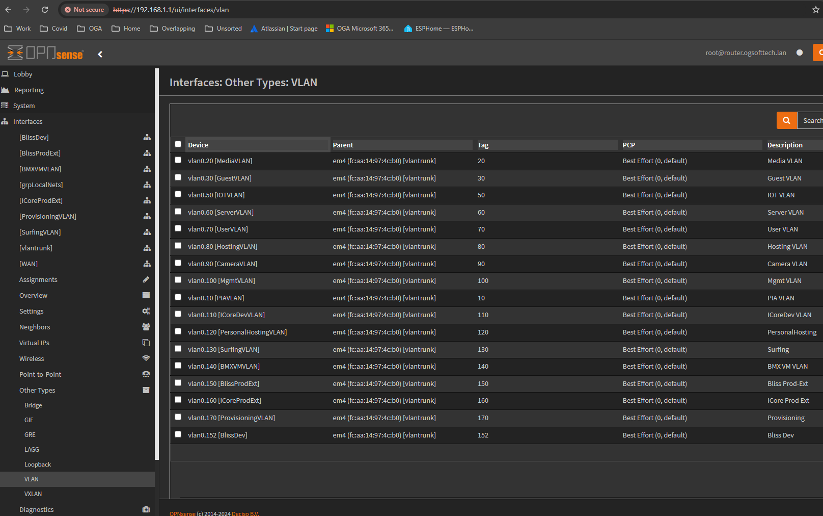
-
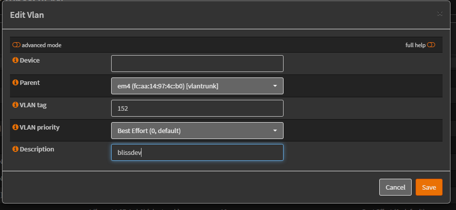
Click the plus sign to reach the new VLAN popup.

-
Leave the Device field blank for now. We will revise it after it is auto-generated.
-
Set the Parent interface as: em4 (our trunk interface from main switch Port 1).
-
Set the VLAN tag to our new VLAN id.
-
Add a description that makes sense.
-
Hit save to add the pending VLAN, but don’t click Apply yet.
-
Reopen the pending VLAN popup by clicking the pencil on the right.
-
Revise the autogenerated vlan Device name to include the VLAN Id, like this:
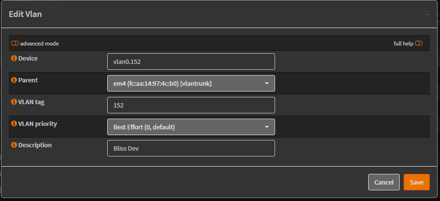
-
Now, click Apply to establish the VLAN interface.
-
Navigate to the Interface Assignments page, at: Interfaces / Assignments.
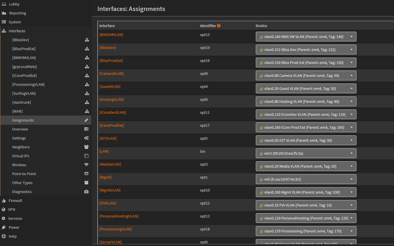
-
Scroll past the listing, to the Assign a New Interface section.
-
Select the new VLAN interface, in the Device field.
It should be colored Green, as ready to add. -
Add a description to it, that makes sense.
-
Click Add, to add the new VLAN interface.
-
Click Apply to accept the change.
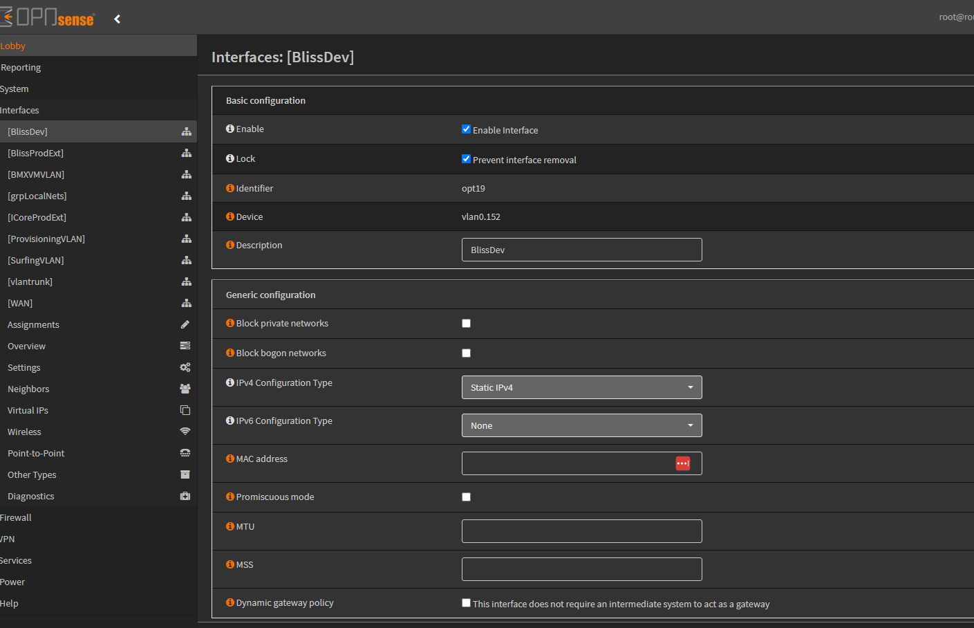
Now, the interface will appear in the upper Interfaces list. -
Click on the name of the interface, so we can update its config.
-
Check the Enable Interface box, so it will be active.
-
Check the Prevent Interface Removal box, so it will not be trivial to delete it.
-
Make sure the Description field is set.
-
We want the router to provide a gateway listener in the VLAN. So we set the IPv4 Configuration Type to Static IPv4.
-
As well. We need to assign a gateway address in the Static IPv4 Configuration block.
We standardize on 24-bit subnets, in 192.168.x.x.
We also standardize on the gateway listening at x.x.x.1.
And, we standardize on the third octet being the VLAN Id for easy identification.
So for example: The gateway address in the 152 VLAN would be: 192.168.152.1. -
Set the subnet size to 24.
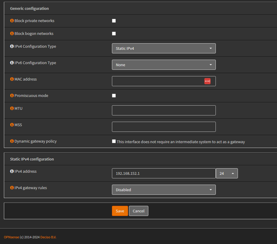
-
Click Save to update the gateway listener.
-
Click Apply Changes so the router activates a new gateway listener for the VLAN.


DHCP Service
Now, we need to setup DHCP and DNS.
Firewall Rules
At this point, we have a VLAN configured across the ESX, main switch and router.
We can put VMs into the new VLAN, and their network adapter (in the new port group) will receive a DHCP address, and can see other VMs in the same VLAN subnet.
But, the VLAN still doesn’t route anywhere, and has no internet access.
So, we will add a few rules to allow DNS, ping, internet access, and last rule isolation.
Ping Across VLANs
-
We allow for most of our VLANs to ping hosts in other subnets.
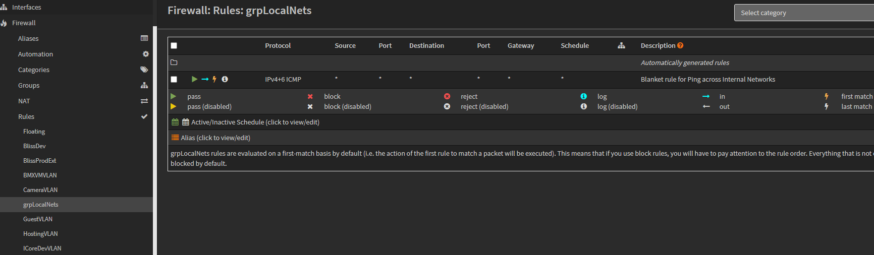
This is allowed through a firewall rule assigned to a firewall group, named: grpLocalNets.
-
If our new VLAN should be allowed to do so, add it to the Firewall group called: grpLocalNets, here:
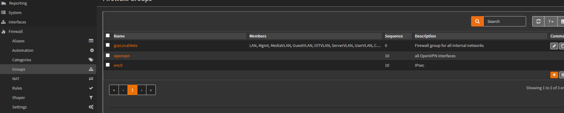
This is done by clicking the edit pencil for the firewall group, and adding the subnet as a group member, by clicking the Members dropdown, and clicking the interface to include it.

NOTE: We purposely DO NOT include some VLANs in this rule.
For example: BlissProdExt and ICoreProdExt are more restrictive in that they expose the prod cluster, inside an isolated network.
The SurfVM, ProvisioningVLAN, and BMXVMLAN are very isolated, as well, and don’t participate.
But, most dev VLANs would be allowed to ping across VLANs. So, they are include as members.
-
Once the VLAN is added as a member of grpLocalNets, click Save and Apply.
DNS Visibility
Machine in the house and house dev clusters use the PiHole DNS instance at 192.168.1.2.
The next steps will provide visibility to the PiHole instance from the new VLAN… if needed.
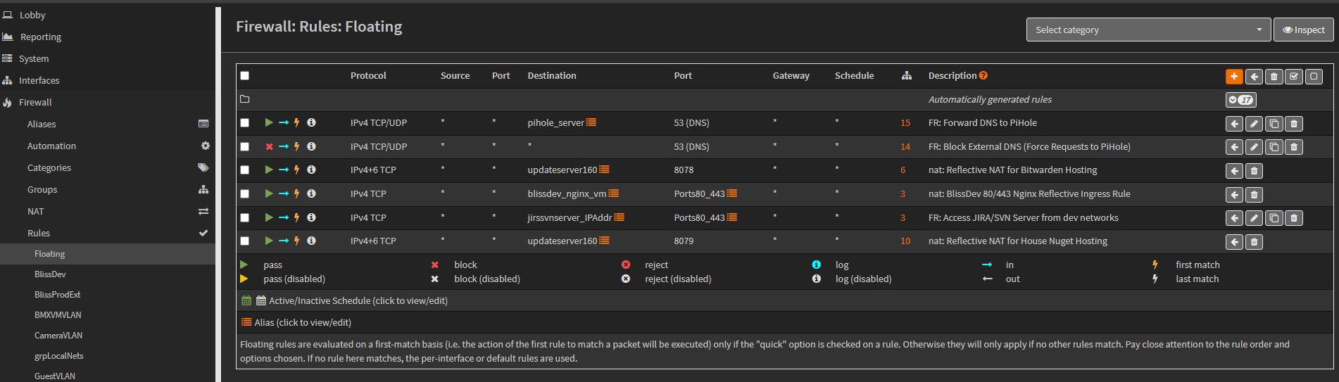
Access to the PiHole instance is granted through a floating firewall rule (one that can be shared across multiple interfaces.
-
To update the floating rule for DNS, navigate to the Floating Firewall rule list at: Firewall / Rules / Floating.
-
Identify the pihole server rule, that says: Forward DNS to PiHole.
-
Click the edit pencil for the rule to open it.
-
Add the new VLAN’s interface as an interface member, by clicking the Interface dropdown and adding a checkbox to the new VLAN interface.
-
Click Save and Apply Changes to finalize the update.

NOTE: Not every VLAN interface is included in this DNS floating rule, like the WAN interface and ProdExt VLANs.
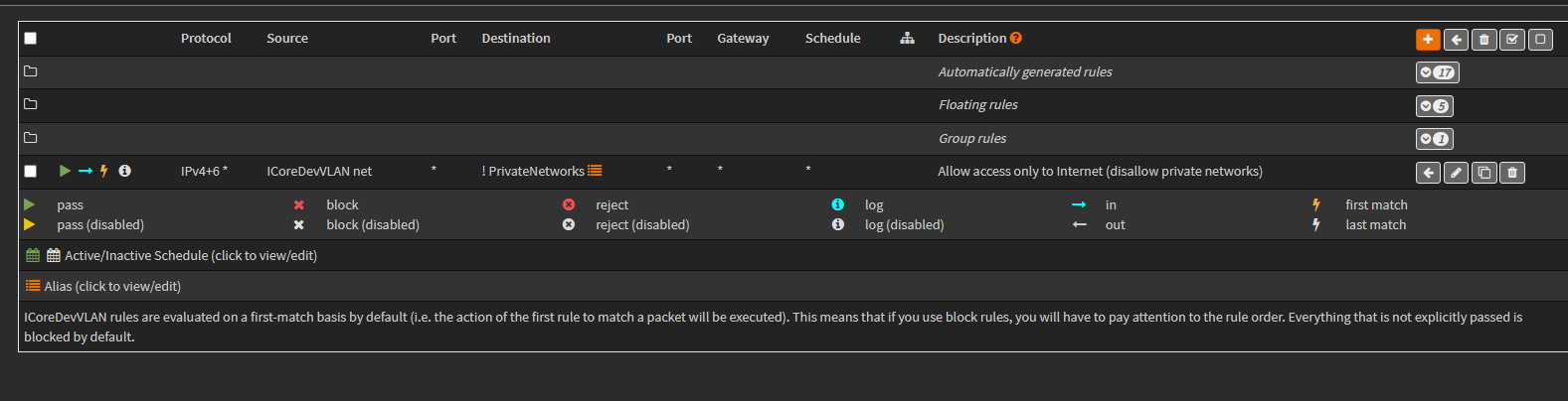
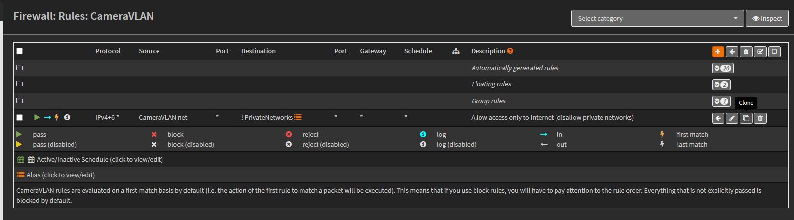
Standard Access External Only Rule (Common Last Rule)
For most subnets, we include a “last rule” that provides internet access, while preventing access to other VLANs. The working idea behind this last rule is that, it sits at the bottom of most subnet rule lists.
It is a single rule that does two things:
-
Allows general internet access
-
Prevents access to other VLANs
OpnSense provide a means for common or shared rules for multiple interfaces (floating and group rules). But, both of those types are listed at the top of a rule list. And, we need a last rule.
So, we have to explicitly add this common last-rule to new subnets.
NOTE: We have a few subnets that are very isolated, with no internet access, such as the Provisioning VLAN or BMXVMLAN. We don’t add this last rule to them, so they get no internet access.
-
If the new subnet will need internet access, add the common last-rule to it by cloning it from another subnet.
-
Navigate to a subnet that has the last-rule, and click the Clone icon.
-
Once the rule copy opens, change the Interface to the new VLAN interface.


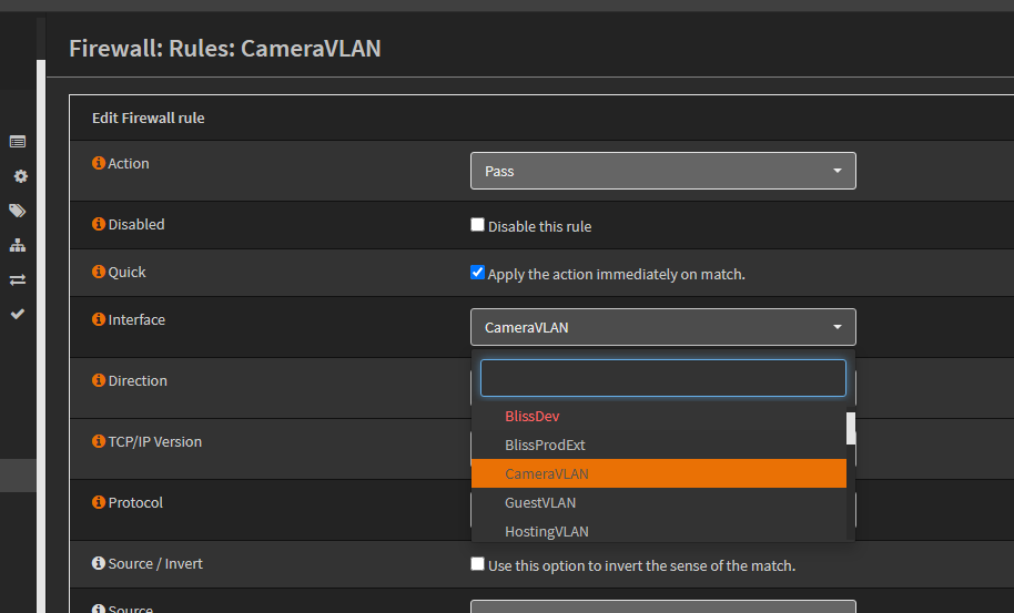
NOTE: These network names are actually firewall aliases that are autogenerated for us.
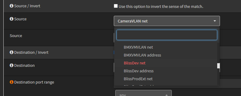
NOTE: Be sure to select the ‘net’ source alias and not the ‘address’ source alias. The net alias is the subnet network range. And, the address alias is the gateway address alias for the subnet.
- Change the Source to the network of our new VLAN.

- No other changes are required. Click Save and Apply Changes to finalize the new rule.


With the new last-rule added, VMs in the VLAN now have internet access with DHCP and DNS, but can’t see other VLANs.
If we want to add access to machines in other VLANs, we simply add rules above this last rule, as it denies what wasn’t already allowed.
Final Notes
The above steps created a routable VLAN with DHCP support, DNS, internet access, and basic isolation.
We can now go ahead and add other firewall rules to access machines in the new VLAN, or for it to reach things like storage and such.